• I learned that I would need to design the mechanical components of a vehicle that would be navigating the Cat’s Conundrum Obstacle Course. There were many possible options for designing but I chose to take inspiration from RC Crawlers to design a capable vehicle.
• The most important aspects of the design were the possible coefficients of friction to gain maximum grip on the track. In addition, calculating the minimum torque required to properly size the motor to the vehicle was necessary.
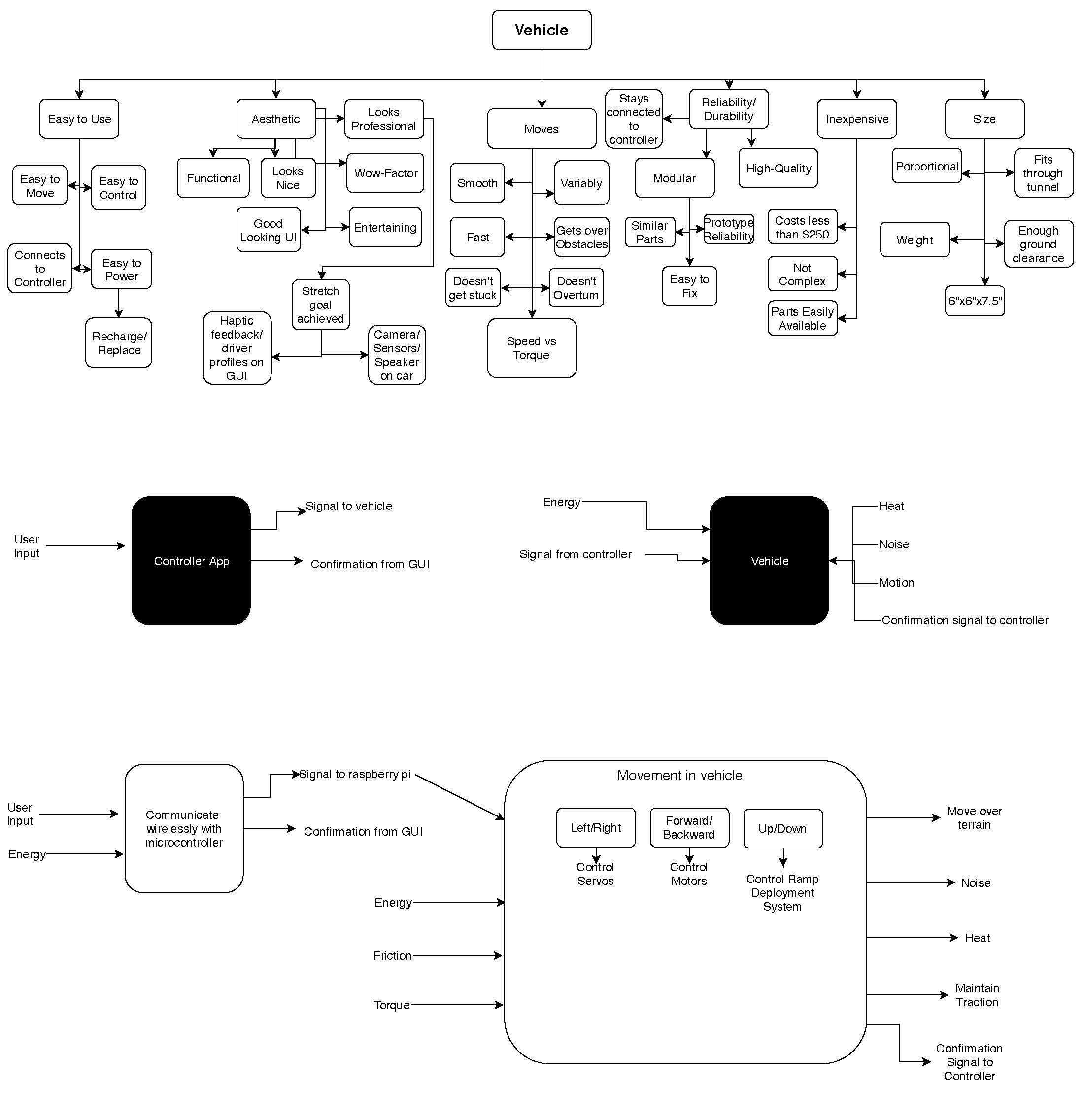
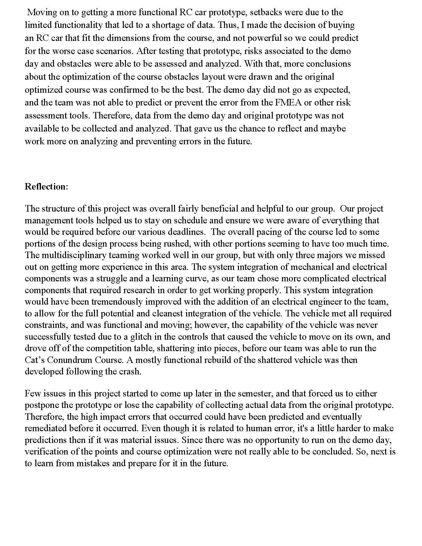
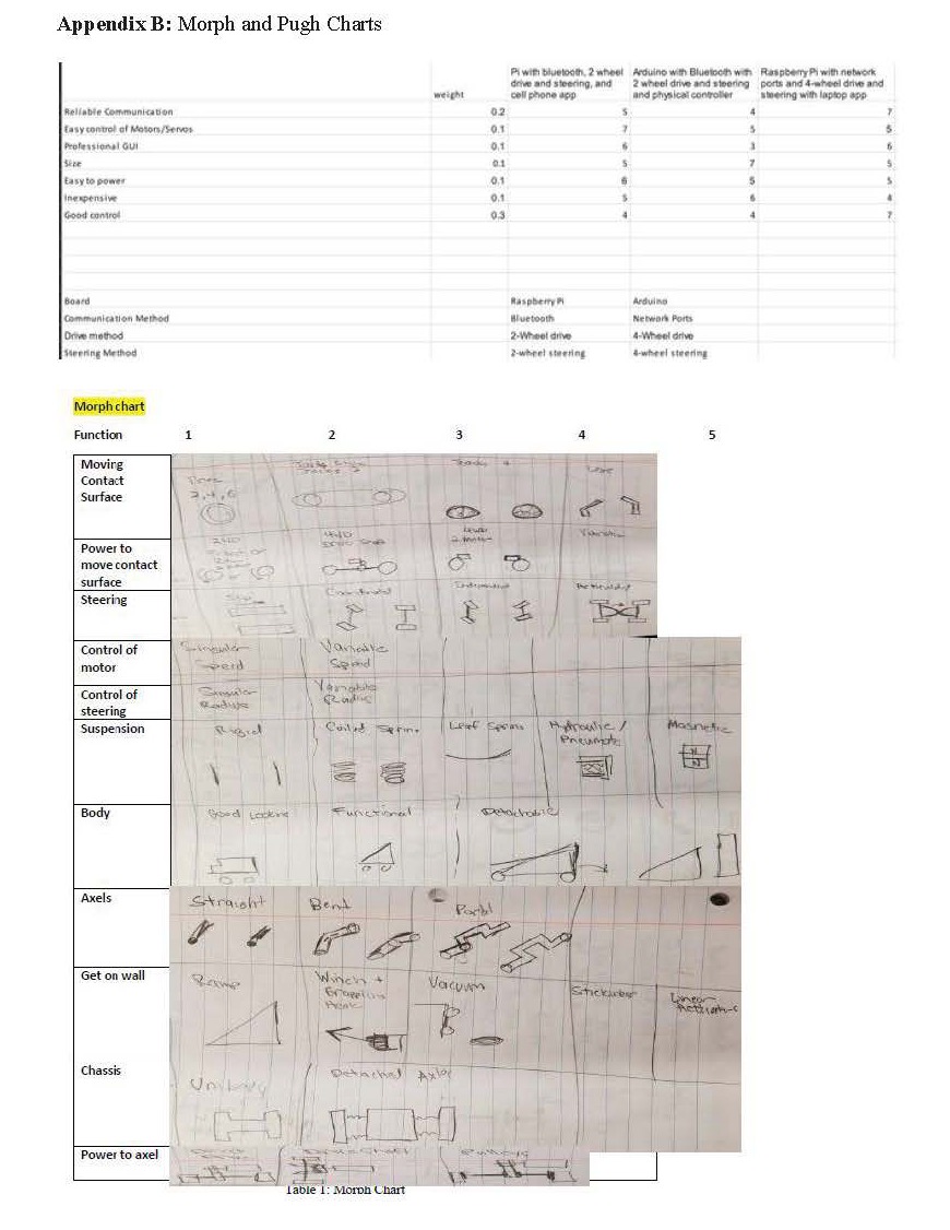
• Top 5 design goals: 4 Independent Tracks, 4-wheel drive via 2 motors and pulley driven axles, variable speeds, independent 4-wheel steering, detached axles from chassis
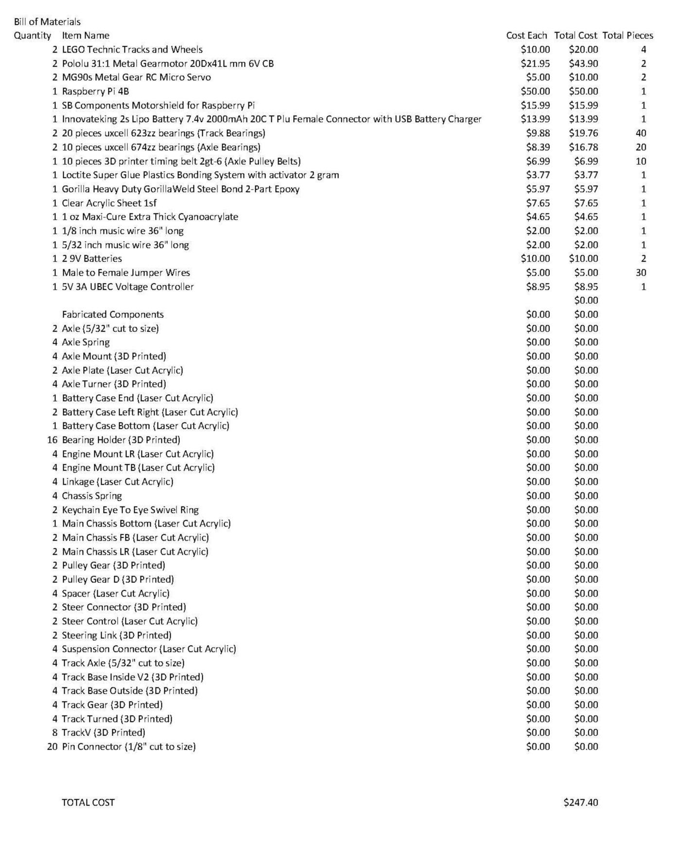
• Constraints: Must be under 6” wide x 6” tall x 7.5” long. Must not fly. Must not spend over $250. Must not damage course in any way. Must be remote controlled.
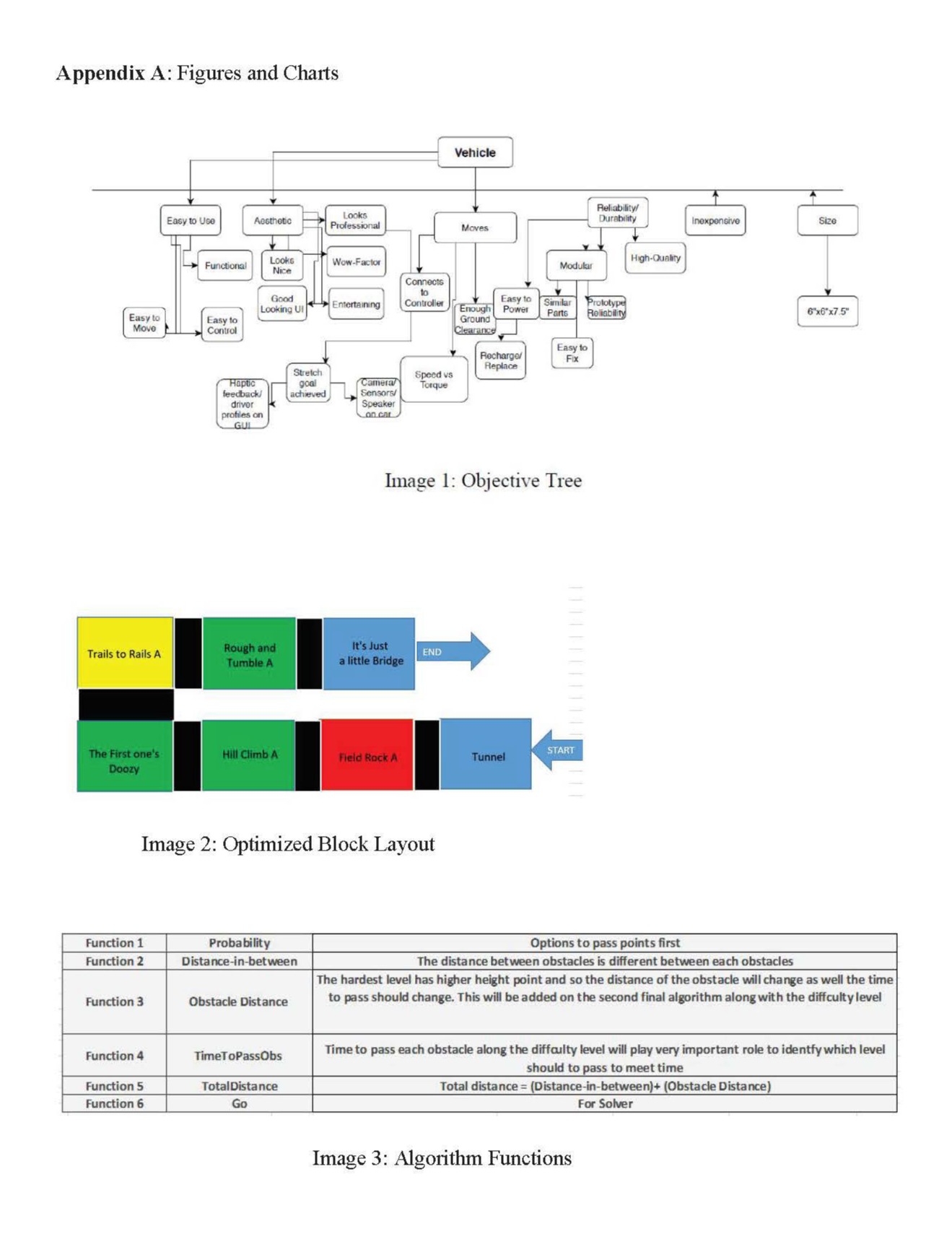
• The vehicle must functionally be able to navigate the Cat’s Conundrum course. In order to do so it must have enough torque from the motors to move the tracks, and the tracks must have enough of a frictional coefficient to grip the course and obstacles. In addition, there must be sufficient ground clearance so the vehicle can pass over obstacles and enough steering so the vehicle can effectively move forwards, backwards, left, and right.
Prototype 1: This prototype had a high mounted motor, the tracks hadn’t been implemented yet, and no chassis nor suspension existed.
Final Prototype 2: This prototype had a lower mounted motor on the axle, the tracks functional and implemented, and a built-out suspension and chassis which allowed some articulation over terrain.
• One main change in our prototype from version one to version two was an added chassis and lowering of the motor on the axle in order to lower the center of gravity and also to provide a location for the electrical components to fit into.
SolidWorks was used to design most components of the vehicle. 3D Printing was utilized for most of the axle and steering assemblies, along with the track assembly. Laser Cutting was used for the body and suspension assemblies, along with the motor mounts and electronic housing.
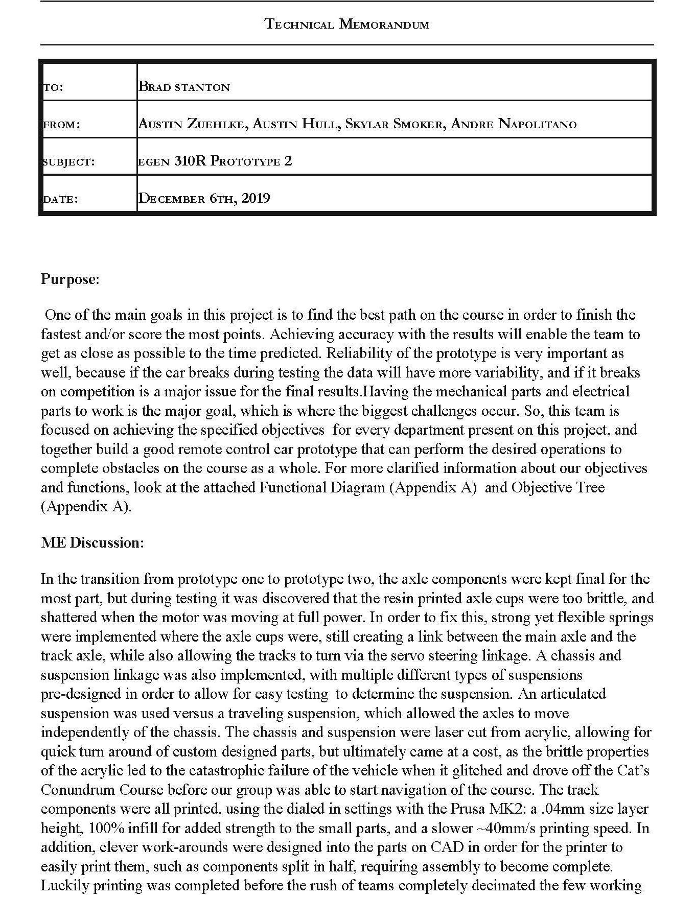
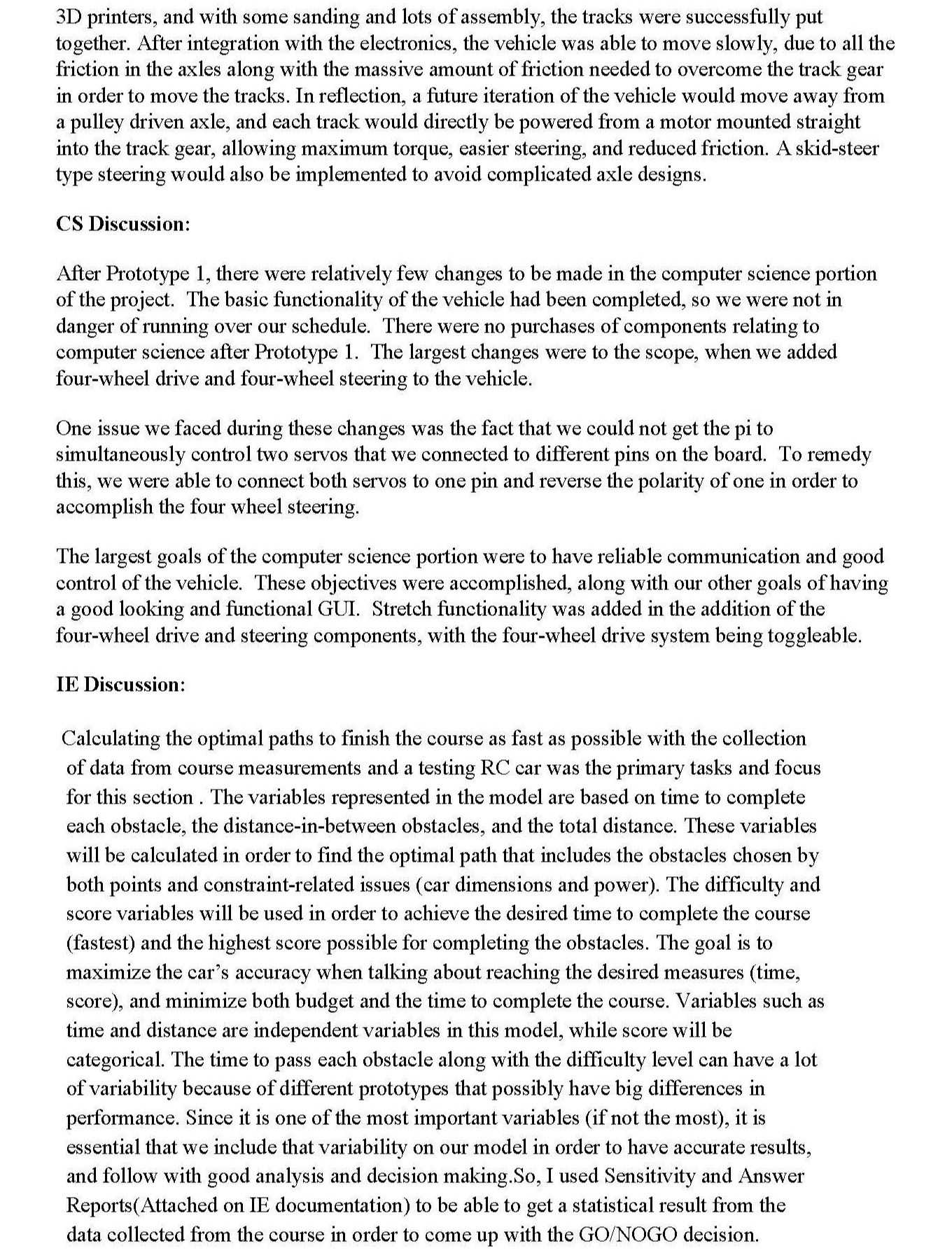
As the mechanical engineer, the design process consumed the majority of my efforts towards this vehicle. My roles as a leader and with project management leaned towards keeping my team members informed about the vehicle design, but I chose to allocate most of the project management to the Industrial Engineer in the group as I saw their abilities as best for effectively managing the project. All in all, I thoroughly enjoyed the class, although our vehicle glitched and drove off the competition table, shattering into pieces before we could run the course.
Designed with Mobirise bootstrap website templates