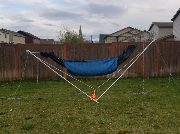
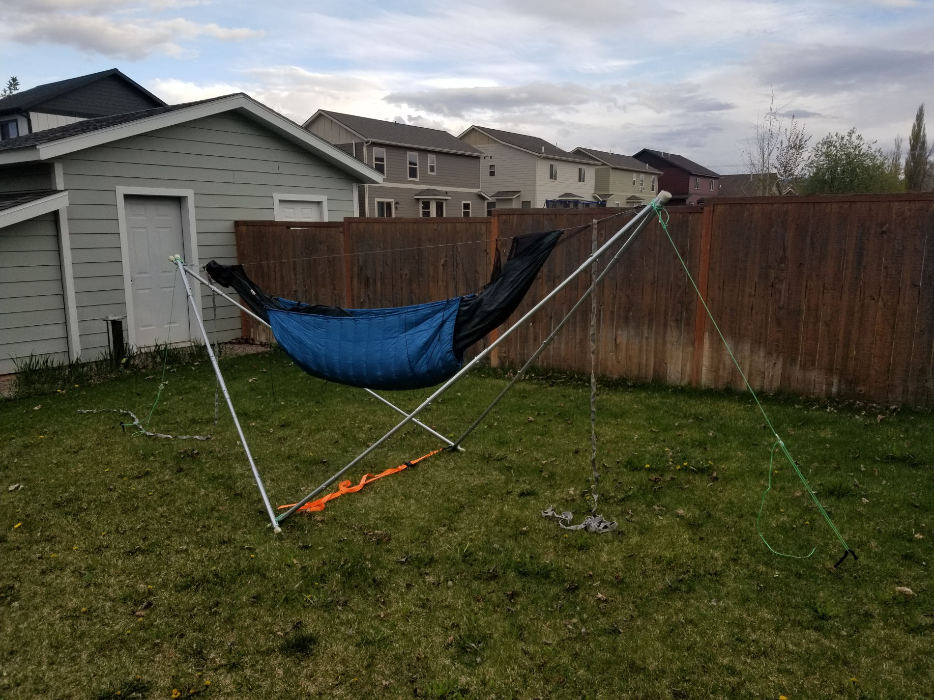
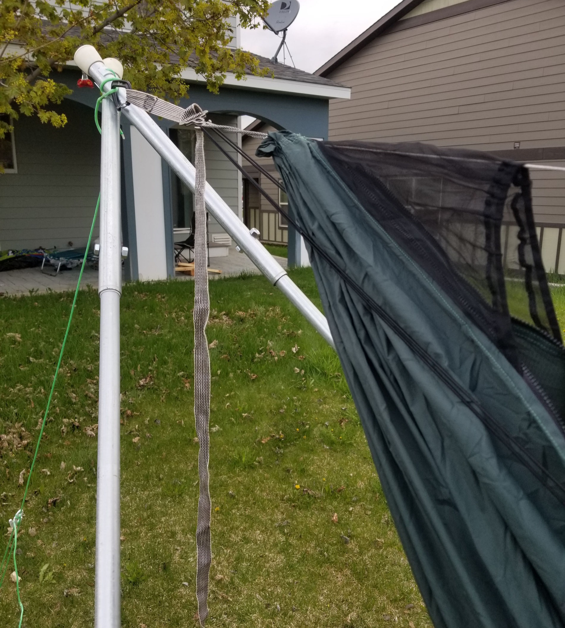
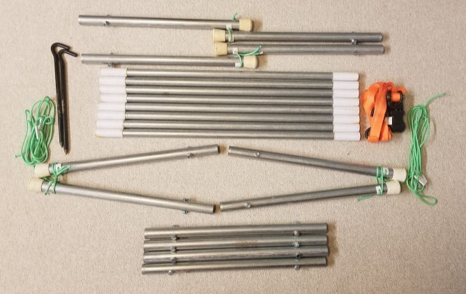
The hammock stand breaks down into 20 pieces, the longest measuring 30 inches, and weighs probably 25 ish pounds.
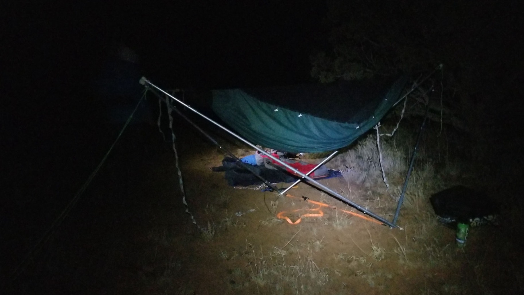
No Trees Required! Using Tensegrity, the hammock stand allows you to hang anywhere you please, which is super useful for camping in high alpine or desert environments, or even in National Parks that aren't keen on hammocks at designated campsites!
A combination of using materials such as EMT Conduit, bolts, and 3D Printing makes this hammock stand solution super affordable compared to other portable hammock stand products.
The two end segments are placed facing each other about 15 feet apart, then each segment is put together alternating the 3/4" and 1" pieces of conduit. Each segment has five pieces, and the segments are connected together by the lashed together end pieces, and lashed together middle pieces. After all segments are properly assembled, use the ratchet strap between the two middle segments to prevent the sides from sliding apart. Ideal length for the ratchet strap is 6', but can be changed to allow for a better hang. At this point, preemptively put a stake into the ground near the end of each side, and loosely wrap the cordage around the stake, allowing at least 6' of slack. Then, set up the hammock between ends of the hammock stand. A ridgeline is necessary in the hammock for the hammock stand to properly work. Once the hammock is set up between the hammock stand, everything should be mostly in place. All that remains is fine-tuning the cordage on each end and tightening it to the stakes so the hammock stand is even. The hammock stand can be used with only 1 stake or even zero stakes but required proper weight management inside the hammock to prevent yourself from being "Taco'd" between the hammock stand, which is embarrassing and potentially dangerous, so using 2 stakes is ideal!
Many resources were available online regarding hammock stand designs that use tensegrity to function. I used many of these designs as inspiration, but none of the designs were as compact as I was hoping to accommodate an 11' hammock and a tarp. I designed four five-piece segments that would all come together to create the hammock stand. I used two 10' pieces of both 3/4" and 1" EMT conduit to construct the hammock stand. The hammock stand was designed with an odd number of segments for a couple of reasons. Primarily, I wanted the middle of each segment to be made up of the 1" conduit to provide a thick enough cross section to resist the bending moment which would be the highest in the middle of each segment. Using the principle of tensegrity, in ideal conditions each segment should have a minimal bending moment applied; instead, the vast majority of the forces are applied axially through each segment. In addition, also having 1" pieces at the ends made it easier to bore holes through to connect each segment.
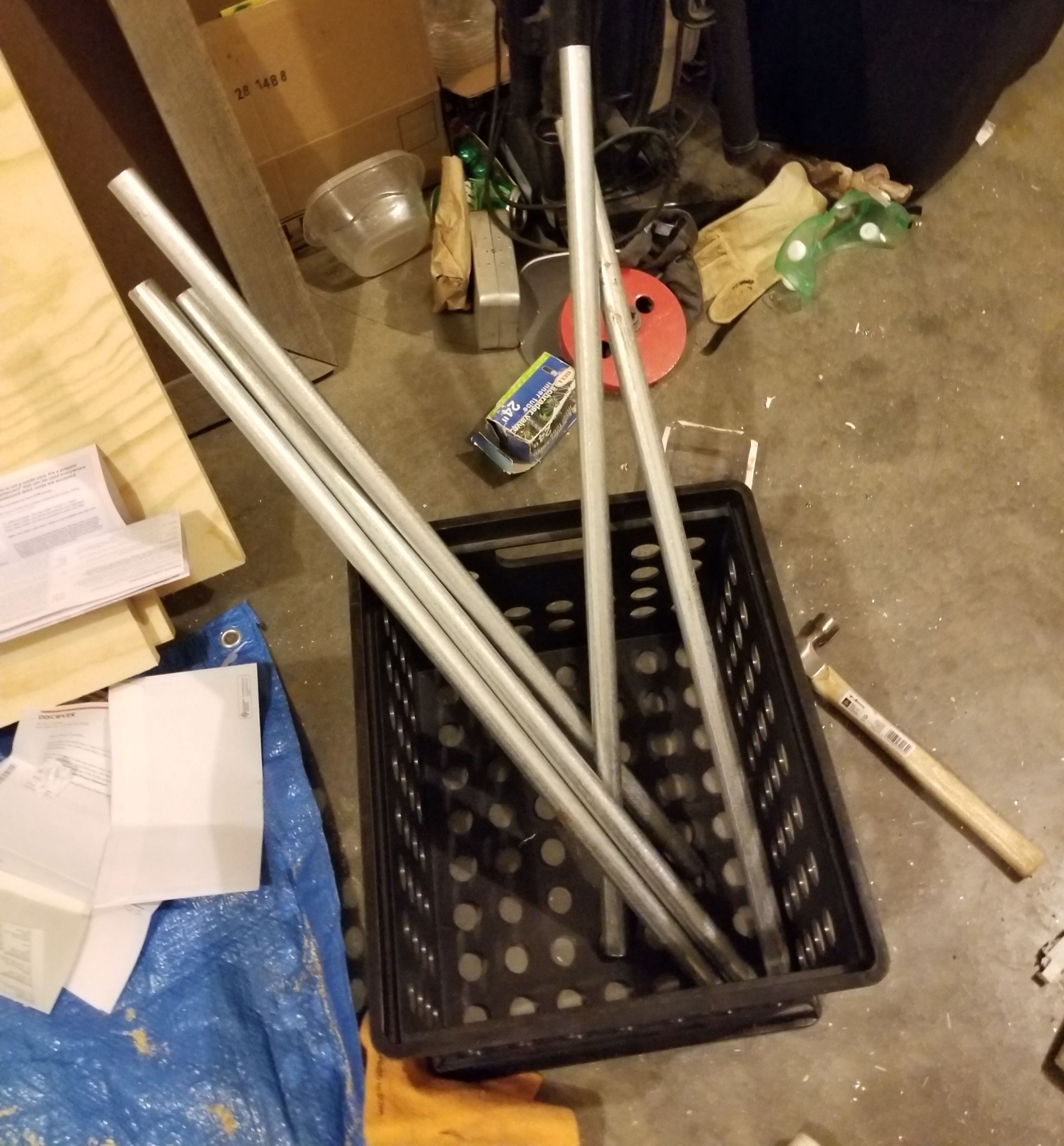
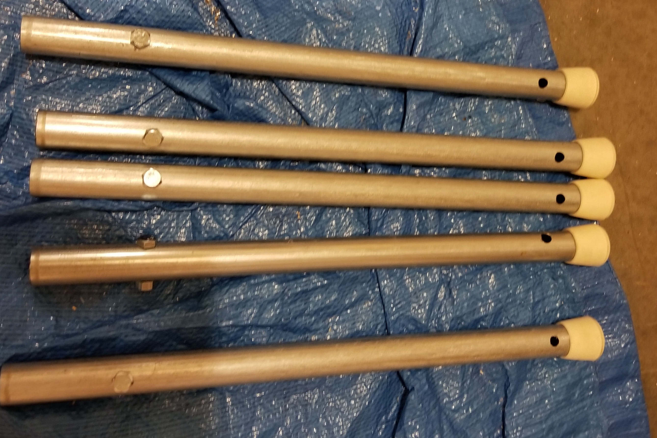
The building process started with taking the conduit and dividing it into segments. The 3/4" conduit was divided into eight 30" segments, which was four 30" segments per 10' piece. The 1" conduit was divided into twelve 20 inch segments, which was six 20" segments per 10' piece. Then each of these segments were cut, and the sharp edges filed down.
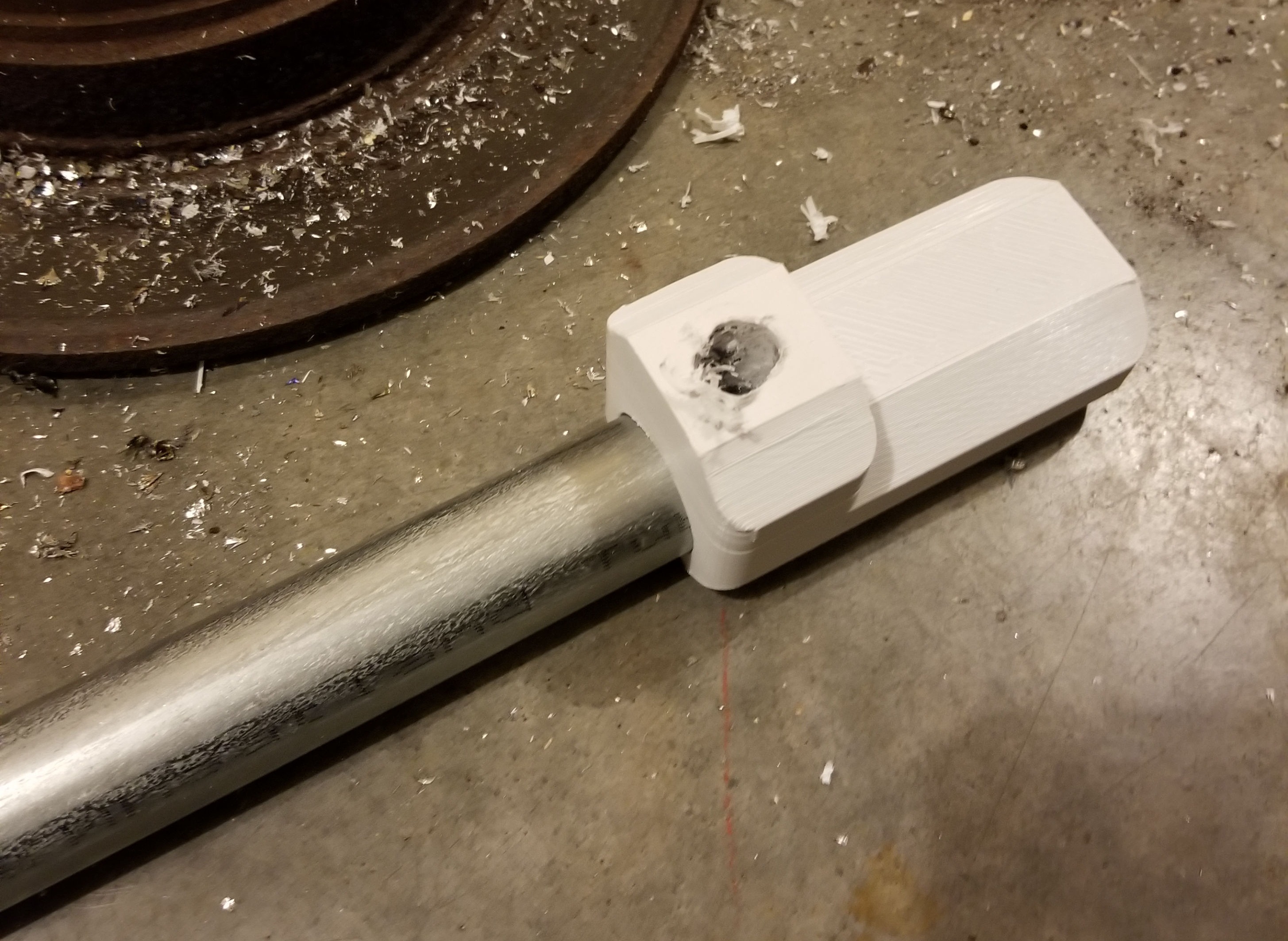
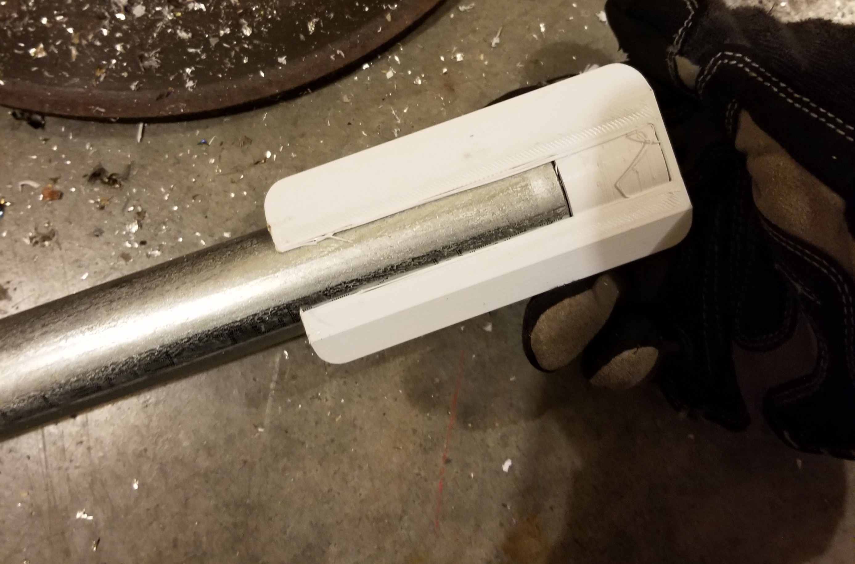
After all pieces are cut to size, set aside 8 of the 20" pieces of 1" conduit. With the other four, use a 3/8" drill bit to bore a hole through each side, at 3" in from the end of the conduit. A jig was designed to drill a hole through the center of the conduit, at exactly three inches, and 3D printed, but didn't necessarily hold up to forces exerted by the drill bit when it caught on the metal.
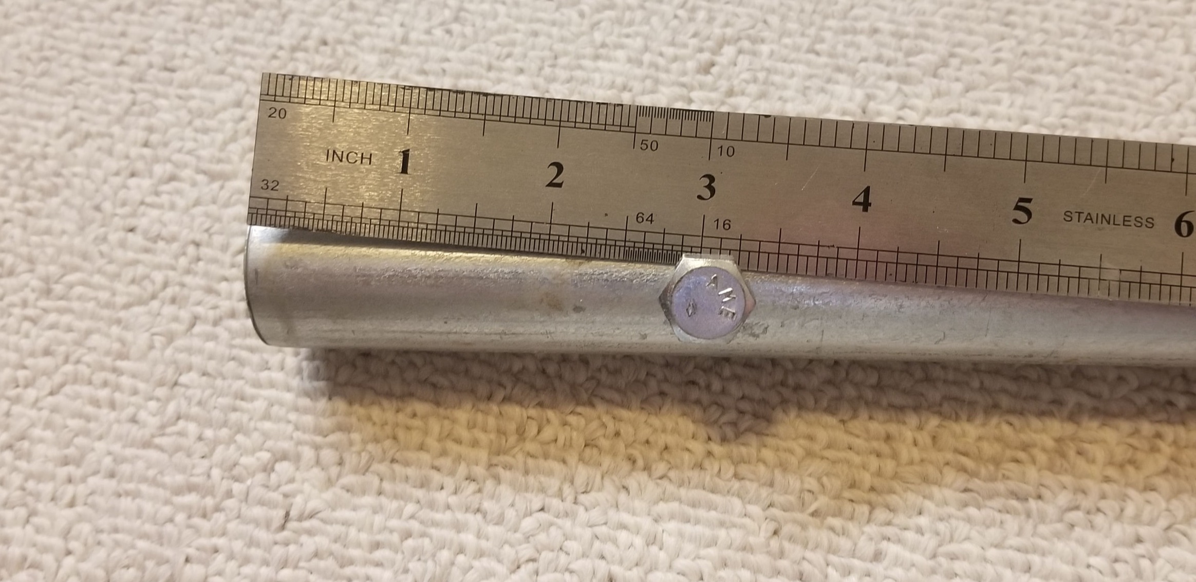
With the other eight pieces of the 1" conduit, use this same jig to drill a 3/8" hole on one side of the pipe at three inches from the edge. This measurement of 3" was chosen to give the 3/4" conduit sufficient surface area contact while being seated inside the 1" conduit.
On the other end of the remaining 1" conduit, a 3/8" hole was drilled through the conduit at 2" from the edge.
A one inch spacer was 3D printed to add to the inside of the jig to modify its use for drilling centered holes in the conduit at 2". Once all the holes were drilled the edges were de-burred.
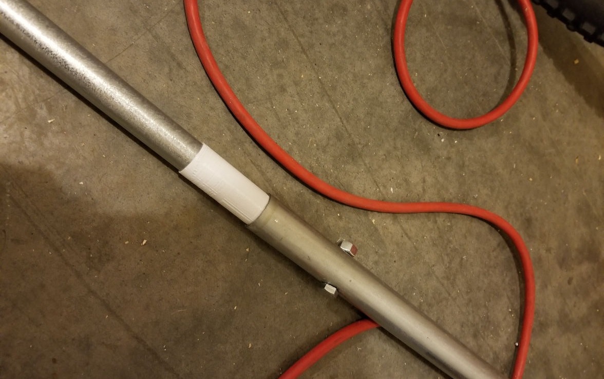
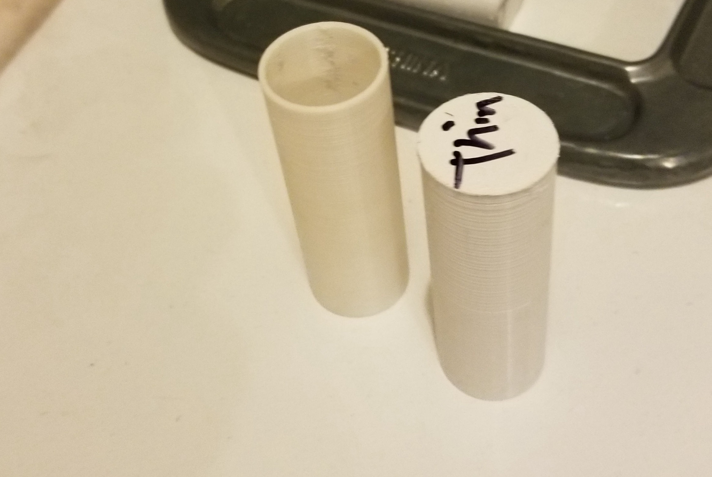
The next stage of the building process was design work on SolidWorks. The OD of the 3/4" conduit and ID of the 1" conduit has an approximately .075" gap, so while the 3/4" conduit is seated inside the 1" conduit there is some wobble and play, allowing some of the forces in the hammock stand to be exerted as a bending moment, and not axial, which is what the tensegrity design relies on. To solve this issue, a spacer was designed to slip over the 3/4" conduit and provide a snug fit. An added benefit for the spacer was a cover on it effectively capped both ends of each piece of 3/4" conduit, preventing debris from entering. The spacers were printed in PLA; however, in use some have had layer separation propagate between the cap part of the spacer and what is fitted around the conduit, so future iterations would be better printed in PETG, Nylon, or even TPU with an emphasis on settings that prioritize layer adhesion over all others. Changing the print orientation would also work, but require more post processing.
1-1/8" end caps were also added to the ends of the 1" conduit on the side where the hole was bored two inches from the edge. This was primarily to keep debris out of the segments and allow for a better contact point between the ground and the bottom of the hammock stand, but also serves to cover the possibly sharp edges of the conduit at the ends of the hammock stand. These were bought at a home improvement store (pre-3D printer), but could easily be designed and 3D printed for different colors or even more optimal designs.
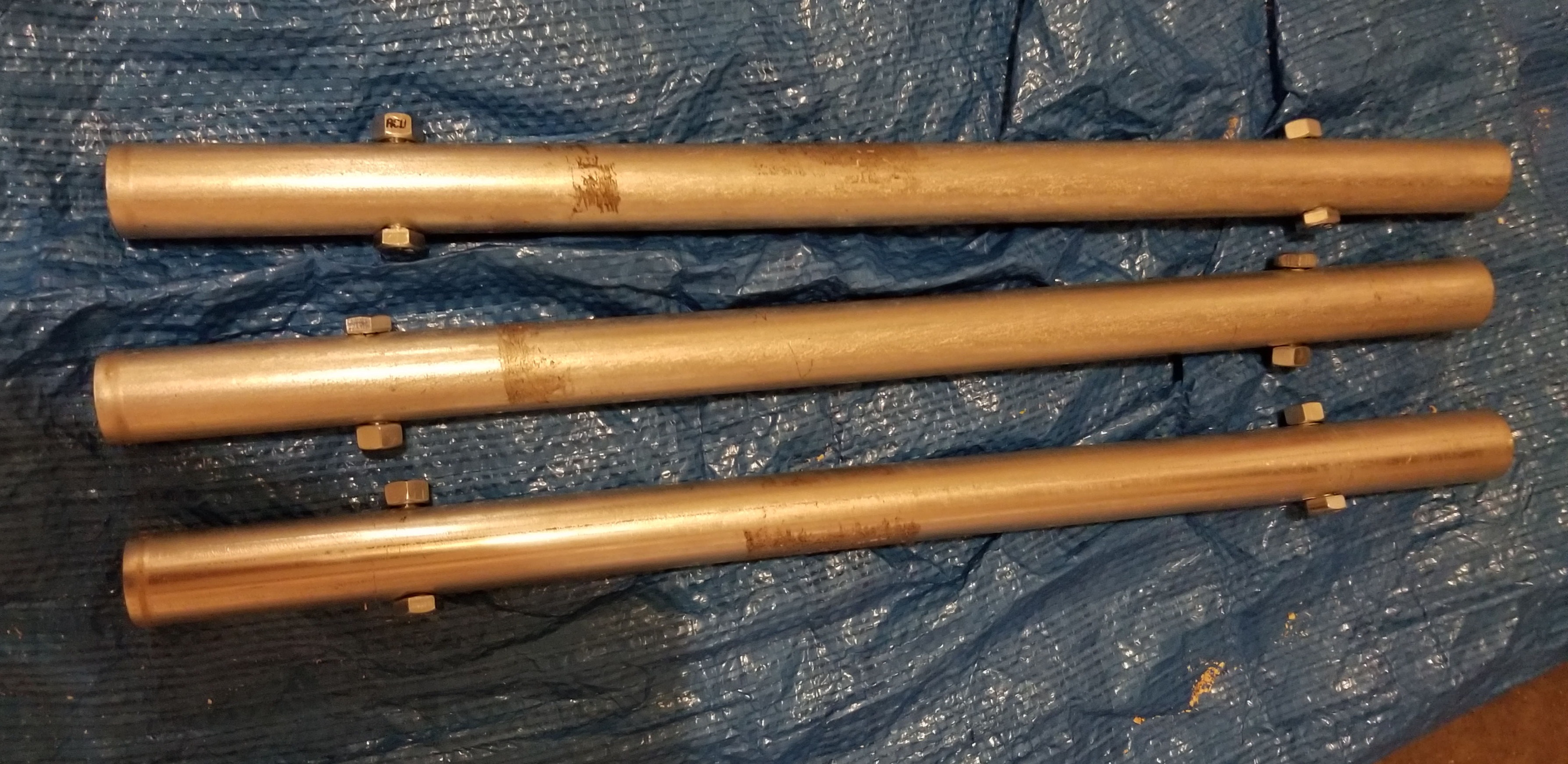
Bolts and nuts were then added to all drilled holes in the 1" conduit that were 3" from the edge. These bolts would be carrying the axial load from the 3/4" conduit and acting as a stop to allow each section to be assembled together. The four middle segments each have two bolts in them, and the bottom pieces and end pieces of the hammock stand each have a single bolt in them.
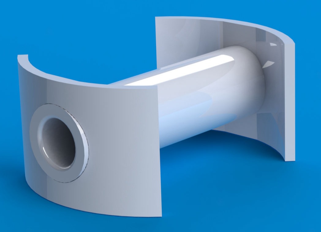
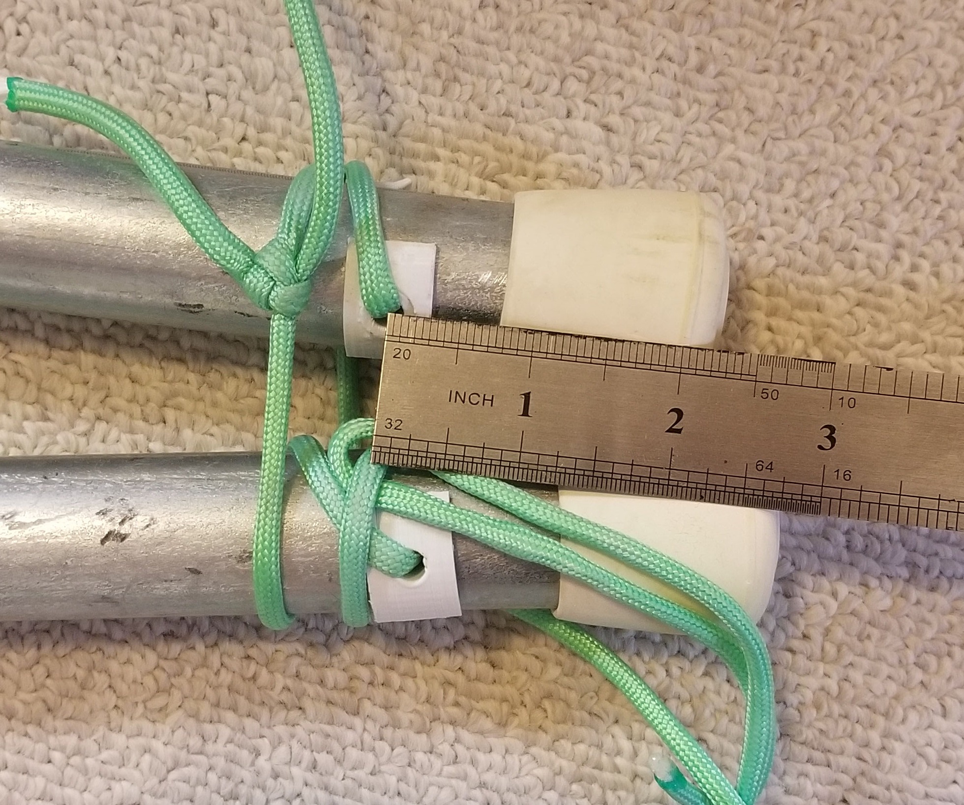
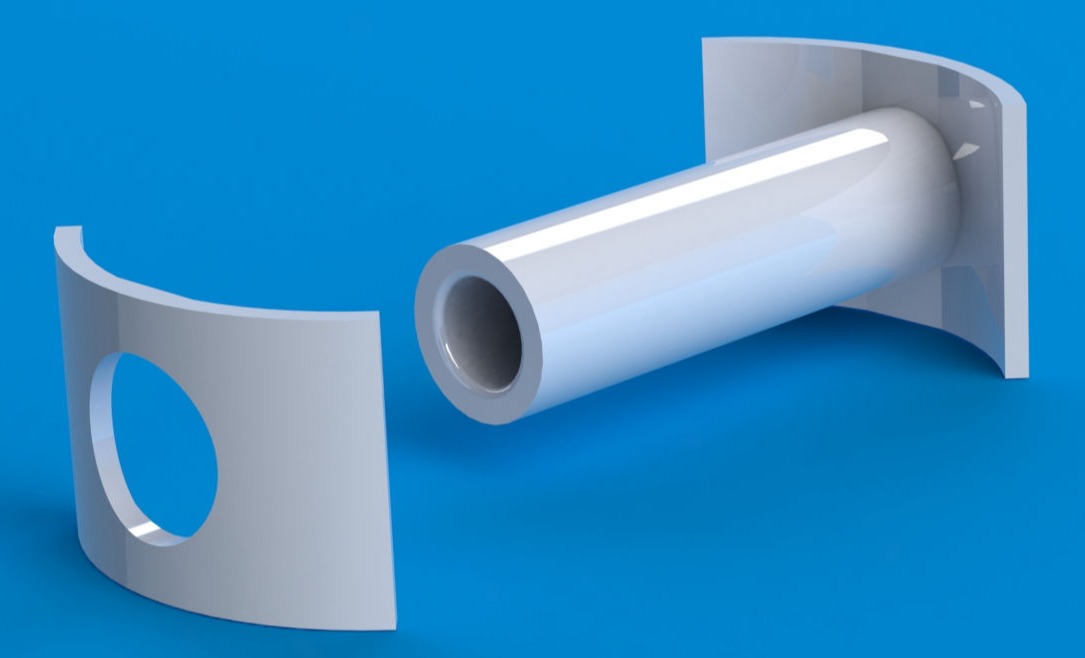
The last part of the design process was creating grommets for the un-bolted holes, as these would serve as holes for the paracord to feed through for lashing each segment together. A simple two-piece design was modeled in SolidWorks, and then printed in PLA. So far, these grommets have worked perfectly. A combination of a slight interference fit and superglue has held the pieces together.
With the eight grommets in place, the final step is to lash each section together. Paracord was used, fed through the grommets, and looped around to connect each section of the hammock stand. Additional paracord was tied to the ends of the hammock stand to be used for tie outs. In the future a carrying bag will be sewn to easily store and transport the hammock stand.
This web page was started with Mobirise template